Welcome to my blog, where I provide comprehensive tutorials on electronics engineering and circuit design. Discover the power of circuit design with easy-to-follow tutorials and unlock your potential in this exciting field. Get ahead in the field of electronics engineering with comprehensive tutorials covering everything from circuit design to practical applications.
"Clutter in your physical surroundings will clutter your mind and spirit."
Whether you are a student, hobbyist, amateur or a professional, it is a good practise to keep your things properly, neat and clean. In this article I will explain the way in which you maintain your discrete electronic components.
As a female I used to keep my things properly, in a well organiser manner. I have a limited space, where I put all my stuff. So I am always looking for organiser, shelves. The purpose of organising your stuff is to store your components, prevent them from dust, keep it away from kids, and you get them back easily when you need them.
All In One Kit:
After a lot of search, I found this kit. I like it very much. Now look at it!!
It seems decent, and economical as well. It is really good for storing discrete electronic components like diodes, resistors, capacitors, transistors, different ICs etc.
“Color is a power which directly influences the soul.” ~Wassily Kandinsky.
Another colorful kit, contains all items (235 pieces) in a single box. It contains wires, LEDs, potentiometers, resistors, capacitors. A good starter kit for beginners.
Resistors and capacitors are most commonly used electronic components. You need to have many different values of capacitors in a circuit. It is good to have a kit for them as well. The kit contains 696 pieces. 24 different values of electrolytic capacitors. Values ranges from 0.1uF to 1000uF and voltage ratings are 10V, 16V, 25V and 50V.
This is the very first law related to electricity. It was presented by German physicist Georg Simon Ohm (1787 - 1854). The importance of this law is evident from the fact that it is still valid and used in almost all the design, troubleshooting and repairing of any electrical system. It is applicable to all linear circuits (a circuit is linear if voltage and current graph is a straight line). It is also applicable to both AC or DC circuits. It describes the relationship between three basic quantities, that is, current, voltage and resistance.
The scientist performed series of experiments, at that time there were no electrical measuring instruments. In today's world we can easily verify Ohm's law because we have measuring instruments.
The empirical law describes the linear relationship between current and voltage.
“At constant temperature, it takes
one volt of electrical pressure (voltage) to push one ampere of current through one ohm resistor”
OR
“At constant temperature, current (I) through the conductor is directly proportional to voltage (V) applied across its terminals”
Mathematically,
I ∝ V
V = I*R
I = V/R
R = V/I
I = G*V
R = 1/G
Where, R is constant of proportionality called resistance. Resistance is inversely proportional to conductance (G). R is same for a single material. The value of R (resistance) depends on material, its dimensions and temperature. I explained temperature dependence of resistances here.
R = ρ*L/A Equation 1
The above equation 1 shows the resistance of a resistor depends on its dimensions ( length (L) and area (A) of conductor).
Rt = Ro (1+ αot) Equation 2
Equation 2 shows temperature dependence of conductors. It is measured in unit Ohms and represented by Greek letter Omega (Ω).
Understanding Ohm’s Law With Simple Analogy
Ohm's Law and its analogy
Beginners are always confuse with theory and mathematical relationships. Here is a simple analogy for Ohm's law.
Consider two pipes of different dimensions (different diameters and hence different area A).
Water easily passes through pipe A because of larger area. It means water passes through less resistive path easily. While in pipe B less water comes out because it offers more resistance for the flow of water.
In this example, voltage is analogous to water pressure. The pipe itself analogous to resistance. It provides the path for the water. If the pipe is narrow, the water flow is less as compared to the broad pipe
Water is analogous to current (electrons) , which flows e region of higher pressure to lower pressure. In the same way current flows from higher potential to lower potential (voltage).
Similarly if consider current ( electrons) instead of water. We get similar observations.
Understanding Ohm’s Law With Simple Experiment
A simple electric circuit is shown. A voltage source (battery) is connected across load resistor (lamp). A connecting wire is a conductor. When circuit is closed, current flows from battery to the lamp, and hence lamp illuminates.
Ohm’s law describes the way in which current flows through the conductor when external voltage is applied From observations we conclude:
The current is directly proportional to source voltage
The current is inversely proportional to the resistance. The higher the resistance, the lower the current
Limitations Of Ohm's Law:
It is valid for metallic conductors only
Metallic conductors obey Ohm's law at moderate temperatures only
All semiconductor devices like diodes, vacuum tubes, transistors, thermistors etc don't obey Ohm's law. They are non-ohmic devices
IV characteristics curve of an ohmic and non-ohmic conductor
Wire wound resistors are the oldest types of resistors. They are suitable for high power and high precision applications. You can imagine the structure of resistor by its name, a spiral helix wound on a tube.
A resistant wire (made from alloy) with high resistivity value is wounded on an insulated core such as ceramic or glass. The value wire wound resistor is determined by this formula,
R = ρ*L/A
The larger the wire the larger the resistance. the larger the cross sectional area, the lower the resistance. To make larger resistance a large thin wire is required.
Pure metals have high temperature coefficient because they are more like to change their resistances as temperature changes. (Effect of temperature on resistance of a conductor). Metal alloys are used because they low temperature coefficient (TCR). They are stable over wide range of temperature. They can satisfactorily work beyond their temperature and power ratings.
For example a wire wound resistor has a operating temperature range is -65°C to +125°C. But it can withstand temperature ranges from -55°C to +150°C.
Similarly a wire wound resistor can dissipate 10 times their rated power for few seconds.
Disadvantages:
Wire wound resistors have inductance as well because of its structure. They possess advantages and disadvantages of an inductor as well including self and mutual inductance. They are not suitable for high frequency applications because of inductive and capacitive effect. In case of overload, the temperature can shoot up to 700°C, before the resistor operation come to an end. It can cause a great hazard if you directly mount a wire wound resistor on a printed circuit board.
Application:
Wire wound resistors are most stable and most expensive types of resistors. They are available in 0.1 to 100 kilo ohm range. They dissipate power up to 10W. They are commonly used as
Circuit breakers or fuses. Since they has high power capabilities, they can use as circuit breakers or a part of circuit breaker
They can be used as potentiometer. For example in stereo system wire wound resistors can be used because of high precision. Another use of such potentiometers are in TV transducers because they can sustainable at high temperatures
Due to inductive property, these can be used as current sensors
What is inside the carbon composition resistors?
Carbon composition resistors are constructed by mixing carbon powder and a non conductive material (for example clay). The mixture is then solidified by heat and compressed in the form of stick or rod. This rod is a resistive element. The whole structure is surrounded by insulated paint with colour codes printing. The leads are made from tinned copper.
Carbon is a good conductor of electricity, more amount of carbon added, more current flows easily. It means the material has less resistance.
The resistance value is determined by
R = ρ*L/A
The amount of carbon mixture
The length of the carbon mixture
The cross sectional area of the carbon mixture
The resistance value is determined by the amount of carbon in the rod. The higher the amount of carbon in the mixture the lower the resistance.
The greater the length of the mixture the higher the resistance.
The larger the cross sectional area of the mixture the lower the resistance.
Specifications:
Resistance range 0.1 ohm to 22 mega ohms
Tolerance 5% , 10%, 20%
Power ratings 1 W
Temperature Range -55°C to +120°C
TCR 1200 ppm/° C
Advantages:
They are least expensive
They are used in audio amplifiers because of their low noise capabilities
Ideal for high frequency application
Disadvantages:
They can only used in low heat dissipation circuits
Not suitable for those applications where humidity and temperature are not important. When these resistors exposed to humidity, water absorption may change resistance value up to +/- 15%
They can not use in high precision applications
Applications:
Carbon composition resistors are widely used in general purpose electronic circuits
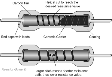
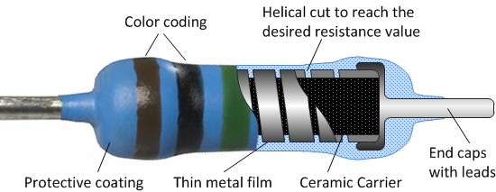
What is inside carbon film resistors?
Carbon film resistors are formed by depositing a thin layer of carbon film over ceramic rod. This carbon film acts as a resistive material. It means it provides some resistance to the current flowing through the material. While the ceramic rod acts as an insulating material, that doesn't allow heat and electricity through it.
The resistance of carbon film resistors is determined by adjusting the thickness of carbon layer and helical cut. This is done by an automated feedback process. The thickness of rod increases and resistance decreases. The resistance value can vary by trimming the carbon film in helical cut (these cuts are spiral in shape). For larger resistance the pitch of the spiral is reduced.
R = ρ*L/A
Let's understand with the help of above equation. The smaller pitch in carbon film provides less path for electrons (more resistive path) while larger pitch in carbon film provides more path for electrons (less resistive path). It means cross sectional area is inversely proportional to resistance. The length of the carbon film increases the resistance because electrons have to travel more.
High negative temperature coefficient of resistance (means the resistance of the material drops with an increase in temperature)
Applications:
Lasers
Radars
X rays
What is inside metal film resistors?
Another type of fixed resistors. A conductive layer deposits on a non-conductive core (usually ceramic core). The conductive layer is a metal film, which is deposited on a ceramic rod.
Did you notice, the construction of metal film resistors are same as carbon film resistors. These days metal film resistors replace carbon film resistor. They don't change their value with age.
The resistance value can be determined by using the formula
R = ρ*L/A
The resistance of a resistor depends on thickness of the deposited metal film (50 nm - 250 nm). The resistance of a resistor can be varied with the length and area of the metal. Different metals have different coefficient of resistivity (ρ). Nickel chromium is a commonly used resistive material. Desired resistance can be achieved by trimming metal film in helical cut. For larger resistance, the pitch of spiral is reduced.
Specifications:
Resistance value 1 ohm to 10 Mega ohms
Tolerance 0.1%, 0.25% ,0.5%, 1% and 2%
Power ratings less than 3 W
Temperature range upto
TCR 50 and 100 ppm/K
Advantages:
Metal film resistors have better tolerance range than carbon film resistors.
Metal film resistors tolerance value upto 2% , while carbon film resistors tolerance value upto 20%
Power Supply For Students | Design Your Own Power Supply | Regulated Power Supply Design
My First Project As A Student Of Electronics Engineering - Design Power Supply
When I was a student of Electronics engineering, this was the first task, that is to design a power supply unit. It might be your first project during the first semester of ECE discipline as well. We are going to design a variable power supply with a maximum output voltage of 24V.
Project Goals & Outline:
What is a power supply unit and why it is important?
Block diagram and explain each block
Circuit diagram and explanation of each component
Choosing the right components
Specifically designed calculators, which help in selecting the right capacitance and resistance
After thoroughly reading this lesson you will be able to design a regulated and variable power supply of desired value. I have designed my calculator, you can calculate the value of the capacitor (filtering or smoothing capacitor), and resistors values (for LM317) according to your need. You can able to select the right components, as I discuss which component is suitable for this purpose.
What is PSU (Power Supply Unit):
A power supply is nothing but a unit for conversion of available AC to DC voltage. The conversion of AC to DC is one of the fundamental concepts of electronics. The circuit consists of basic components like diodes, capacitors and a capacitor. In this post, we have to design a regulated power supply, so we add a regulator IC (i am going to use LM317).
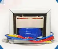
Choosing the right transformer for step-down AC voltage:
Here the purpose of the transformer is to step down the available AC voltage. You get AC voltage from your socket which is equal to 240V or 120V.
How do you choose the right transformer?
I am not going into the details of the transformer. Transformers have standard ratings. You can not build a transformer of your own choice. It is the art to choose the right transformer. As a beginner, it is quite difficult for you to choose the right transformer. Please carefully read my guide, it may help you. First of all, decide what would be the output voltage of your power supply. In my case, I decide to make it 20V. It can regulate voltage from 0 to 20V. There are transformers available, which can step down output 24V AC. (Other ratings are 12V, 18V etc). The output of the transformer depends on its primary to secondary turns ratio. You can calculate the estimated output by using this formula,
NP/NS = VP/VS
Where
NP = Number of primary winding turns
NS = Number of secondary winding turns
VP = Voltage at primary windings
VS =Voltage at secondary windings
With the help of this formula, you can calculate the primary to secondary turns ratio (NP/NS)
Example#1:Evaluate NP/NS ratio, when incoming AC voltage is 120V, and step down up to 20V
VP = 120V
VS = 20V
NP/NS= 6
Example#2:Evaluate NP/NS ratio, when incoming AC voltage is 240V, and step down up to 24V
Please handle it with care, you can get an electric shock. Please first use any relevant CAD software, to design your project, then come to hardware components.
Power Supply - Schematic diagram and block diagram
The rectification process for AC to DC conversion: This block performs two tasks. The first is rectification. After rectification, the output is fed to a smoothing or filtering capacitor. We will first discuss the bridge rectifier and then the smoothing capacitor.
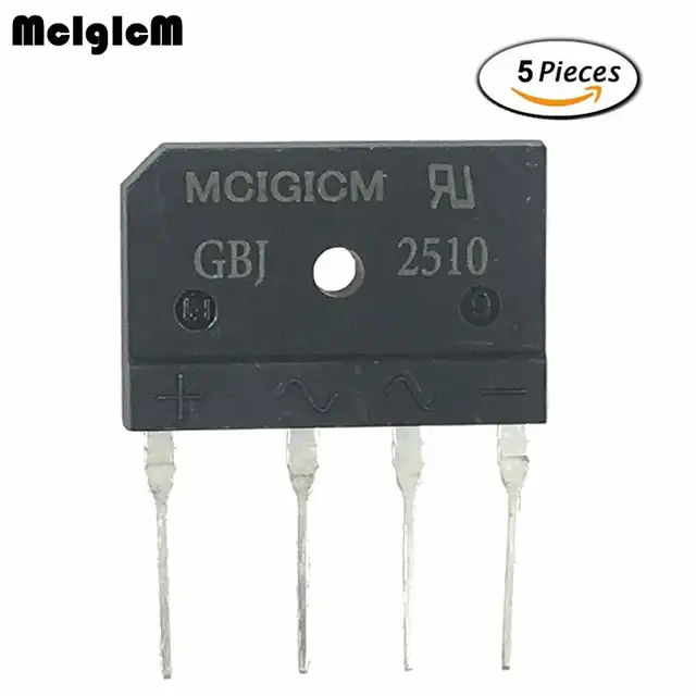
Needless to explain rectifier block, as is already discussed in detail here. This is the heart of the whole system. It consists of four diodes, which convert AC to pulsating DC. Bridge rectifier IC is available, however, you can use four discrete diodes as well. GBJ2510 is a bridge rectifier IC.
You get 24V from secondary windings of the transformer
After rectification, you get pulses, with a peak value of 22.6V
We consider diode drop which is equal to (0.7+0.7)V
We have to eliminate the pulses, so let's come to the next part of this block
While designing your circuit, you might confuse about component selection. You can use discrete diodes for this purpose. But it is recommended to use a bridge rectifier IC. There are bridge rectifier IC available in the market. MCIGICM 25A 1000V diode bridge rectifier gbj2510
What does a bridge rectifier IC look like?
Specifications of GBJ2510
This block also contains a capacitor. The capacitor smoothes the pulsating DC voltage. This is the smoothing capacitor or filtering capacitor. To get ripple-free voltage, you need to select a proper capacitance value. The discharging time of the capacitor should be high.
Choosing a smoothing capacitor is also a little bit tricky.
The first time you might have rippled output, but don't worry
You just have to adjust the capacitor value, once you get the appropriate capacitor, you get the smooth DC
I discussed this equation in a full-wave rectifier. The equation is helpful for the evaluation of the capacitance value.
Note: the above formula is only valid if the ripple voltage value is not more than 20% of the peak voltage.
I designed a calculator, input appropriate values, you get the desired value of the capacitor.
Volt
Volt
Ohm
Hertz
farad
The Regulator Block:
The voltage regulator maintains a constant voltage level at the output irrespective of no load or full load condition. This block is added in between input and output. It resists any change in input voltage and output load and maintains a constant voltage.
We are using LM317 as a positive voltage regulator. Its specifications are
Adjustable output voltage ranges from 1.25V to 37V
Input voltage ranges from 3 to 40V
Output current 1.5A
Look it is a three-terminal device. As a beginner, you can easily use it in your circuit.
Look at the regulator block. It consists of LM317, two resistors (R1 and R2) and two capacitors (C2 and C3). The capacitors are decoupling capacitors. The resistors make a voltage divider circuit. With the help of these resistors, we can adjust the output.
Designers recommend it is better to set R1 = 240,
There is a targeted output voltage Vout, which is equal to 20V in this case. With the help of the given formula, you can calculate R2.
Here is a calculator, you have to enter any two variables, and it will evaluate the third one.
Ohm
Ohm
Volt
Conclusion:
I hope you understand the working and operation of the power supply circuit. It is one of the basic circuits. You can find a variety of circuits. If you would able to properly design your power supply unit, then this will power your electronic projects in future.
Some of my favourite books are given below. I always use these books before preparing notes. I recommend all beginners to use these books to master analog electronics. All of them are my favourite.


 . It is really helpful to sort different resistors.


.jpg)


.jpg)

