Showing posts with label Operational Amplifiers. Show all posts

Inverting Amplifier Op Amp - Analysis & Examples

Usually, Op Amp isn't used in an open-loop configuration. The Opamp is connected to some passive elements and forms a feedback circuit. The feedback can either be positive or negative, depending upon the connection. If the output is connected to the inverting terminal of the Opamp then this is known as negative feedback. Now, there are two such configurations, the inverting configuration and the non-inverting configuration. When the input signal is applied to the inverting ‘-’ input terminal of the Opamp then it is known as inverting configuration. When the input signal is applied to the non-inverting ‘+’ input terminal of the Opamp, then it is known as a Non-inverting configuration. 

The inverting configuration or amplifier serves as a basic module for designing even more complex op-amp circuits. It is simple to implement, the non-inverting input is grounded. There is a voltage source connected to the inverting terminal through the input resistance Rin. There is a feedback resistor Rf connected between the output and inverting terminal of the op-amp. It forms a closed loop around the operational amplifier. The output is 180° out of phase or inverted as that of the input signal. 

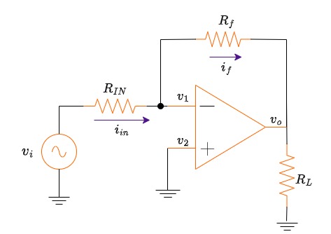
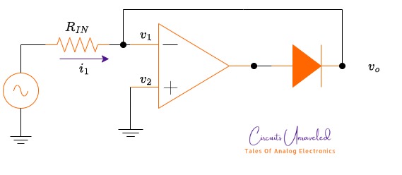
Now, let's analyze this circuit. The aim is to find out the relationship between output voltage vo and vi or the gain of the amplifier.


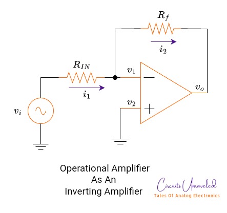
For an ideal Op Amp, we should consider the virtual ground concept. That is, the non-inverting terminal is tied to the ground. It is physically connected to the ground. However, the inverting terminal is at the virtual ground but not physically connected to the ground. We consider this because of the infinite open loop gain of the Opamp. 


Similarly, for an ideal Op Amp we should consider the input resistance of the Op Amp is infinite. No current flows through the input terminals of the Opamp. Hence the input current i1 = if. No current flows through inside the Opamp. 


Apply KCL at the node 1. 

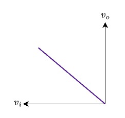
This is the required closed-loop gain. It simply depends on the external resistors. The minus sign shows the signal inversion at the output. 

Inverting Amplifier With Compensating Resistor R:

There is another way of implementing an inverting amplifier, it is given below. In this configuration, there is a resistor known as a compensating resistor. This resistor is commonly denoted as RC. For inverting configuration, this compensating resistor is equal to:
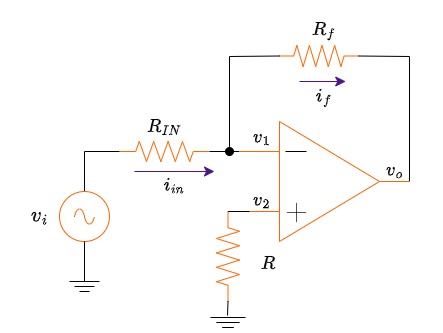


Given:

Rin = 1kOhm

R = 1kOhm

Rf = 10kOhm

Calculate the gain.

There is no effect of a compensation resistor on the gain.

Inverting Amplifiers With Load Resistor:

Given:

Rin = 1kOhm

R = 1kOhm

Rf = 10kOhm

Calculate the gain.


Inverting Amplifier Another Configuration:
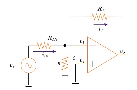

Given:

Rin = 1kOhm

R = 1kOhm

Rf = 10kOhm

Calculate the gain.


Don't get confused with the extra resistor. Start your analysis with the same method. Apply KCL at node A.


So, there is no change in the value of gain.


Frequently Asked Questions:

What are the advantages of inverting amplifiers?

It has less input impedance, because of the feedback resistor. In comparison with the open loop configuration, the input signal directly applied to the inverting terminal has much greater input resistance than the closed loop inverting configuration. The input resistance only depends on the external resistors. 

What are the disadvantages of inverting amplifiers?

Its input resistor is the biggest disadvantage as well. If an application calls for a higher input impedance, both Rin and Rf have to be greater enough. For example, to minimize signal source loading, greater values of resistors are required. However, larger values of input resistors increase offset errors which arise due to amplifier bias current.

Why is it called an inverting configuration?

The output signal is out of phase. The amplifier reverses the phase angle of the output and hence input and output are 180° out of phase with each other. 

What is the purpose of a feedback resistor? 

It determines the gain or amplification factor of the amplifier. The higher the value of the feedback resistor (Rf) as compared to the input resistor (Rin), the higher the gain of the inverting amplifier. 

What are the applications of inverting amplifiers?


It is commonly used in precision scaling applications, audio processing, active filters, voltage-controlled oscillators, and instrumentation amplifiers for sensor interfacing. 

What is the transfer function of inverting amplifiers?

The transfer function (Vout/Vin) of an inverting amplifier is given by the formula:


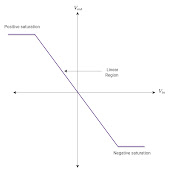
What is the maximum output of an inverting amplifier?

The maximum output voltage is limited by the power supply of the Opamp. If the external supply is ± 12V, the Opamp will saturate after this voltage. Similarly, if the supply voltage is ± 15V, the output voltage swing is limited by the power supply voltage.

Conclusion:

I have analyzed all four circuits, and they are quite similar to each other. I try to make sure that I have cleared up all the concepts in every possible way. 

Precision Half Wave Rectifier |

 Operational Amplifier Based Half Wave Rectifier:

Rectification is a process of converting an AC waveform into a single-direction pulsating DC. There is a filter block at the end of the rectification block. The purpose of this filter is to smooth the DC voltage (which is in the form of pulses). 


The process of rectification 

Diode-based rectifier circuits are commonly employed in power supply designs. In these applications, the voltages being rectified have much greater values than the voltage drop of a diode. Passive rectifiers are suitable for large signals coming from transformer windings.

In some cases, like instrumentation applications, signals coming from sensors or transducers are of very small value in the order of millivolts. In these applications, it is impossible to employ diode rectifiers because of tiny signals (less than 0.7 V). So, here comes the concept of precision rectifiers.


What is an active rectifier?

There are many ways to implement active rectifiers. But I am going to discuss opamp-based precision rectifiers. I will discuss the half-wave precision rectifier in this post. Diodes along with Opamp form a special class of rectifiers known as precision rectifiers.

Precision Half Wave Rectifiers:

It consists of an Opamp and a diode in the feedback path. The input signal is at the Non-inverting terminal of the amplifier.

The circuit works as a voltage follower during the positive half cycle only. 

vO = vi   for vi >= 0

The relationship between the input and output of the given circuit.

During the positive half cycle of the input signal, the output is also positive. The diode starts to conduct and a perfectly positive half cycle appears at the output. During the negative half cycle, the diode remains off.

OpAmp based half wave rectifier

This circuit has some limitations. The biggest drawback of this circuit is the feedback loop. Have a look at the circuit. The feedback loop will open when the diode is off (in this case during the negative half cycle of the input signal, the diode turns off). Hence Opamp gets saturated. In each cycle of the input signal Opamp switches from the linear region and the saturation region.

Improved Circuit: Precision Half Wave Rectifier With Two Diodes:

To avoid the switching of Opamp from linear region to saturation region, again and again, this circuit is useful.


The improved and faster circuit for half wave rectification.


In this circuit, there are two diodes and two resistors along with the Opamp. The input signal is applied to the inverting terminal. In this circuit, there is negative feedback that never gets open and won't let the Opamp to saturate. During the positive half cycle of the input signal, D2 is conducting. The output of the amplifier is negative (because of the inverting configuration), and the D2 is off during the positive half cycle. 


During the negative half cycle, the D2 I'd off. The output of the Opamp is positive. The anode of the diode D1 is at the positive potential and starts to conduct and establish negative feedback through R2. The current flows through R2 is equal to the current flows through R1. 


For R1 = R2, the transfer characteristics will be

vo = - vi   for vi <= 0

The relationship between input and output of the given circuit.

The prominent advantage of this circuit is that the feedback loop is closed throughout the circuit operation. D2 is included and hence the feedback loop remains closed.

Active Vs Passive  Rectifiers: | Difference Between Active and Passive Rectification:

So, let's discuss the difference between active and passive half-wave rectification. As a beginner, you might not be aware of the active rectification and passive rectification.  

Passive rectifiers use simple silicon diodes to convert alternating current (AC) into direct current (DC). It is composed of a simple diode, followed by a load resistor.


A silicon diode is effectively converting AC to DC


A diode is a unidirectional device that allows the flow of current only in one direction hence effectively converting AC into DC. For practical diodes, there is a forward voltage drop of 0.7V (for a silicon diode). They are suitable for rectification of large voltage signals. 


What will happen if the input voltage is 1V, after rectification from a passive rectifier, the output voltage becomes 0.3V (there is a diode drop of 0.7V). 


In this case, active rectifiers are used. They will effectively convert small AC voltages into DC voltages. They are composed of super diodes ( A super diode consists of an Opamp followed by a diode. The basic active rectifier consists of a super diode that is an operational amplifier and a diode. The negative feedback and high gain are responsible for bypassing the diode’s threshold voltage.


Comparison between output of an active (precision) rectifiers Vs passive rectifiers 


Popular Posts