My First Project As A Student Of Electronics Engineering - Design Power Supply
When I was a student of Electronics engineering, this was the first task, that is to design a power supply unit. It might be your first project during the first semester of ECE discipline as well. We are going to design a variable power supply with a maximum output voltage of 24V.
Project Goals & Outline:
- What is a power supply unit and why it is important?
- Block diagram and explain each block
- Circuit diagram and explanation of each component
- Choosing the right components
- Specifically designed calculators, which help in selecting the right capacitance and resistance
After thoroughly reading this lesson you will be able to design a regulated and variable power supply of desired value. I have designed my calculator, you can calculate the value of the capacitor (filtering or smoothing capacitor), and resistors values (for LM317) according to your need. You can able to select the right components, as I discuss which component is suitable for this purpose.
What is PSU (Power Supply Unit):
A power supply is nothing but a unit for conversion of available AC to DC voltage. The conversion of AC to DC is one of the fundamental concepts of electronics. The circuit consists of basic components like diodes, capacitors and a capacitor. In this post, we have to design a regulated power supply, so we add a regulator IC (i am going to use LM317).
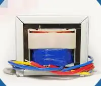
Choosing the right transformer for step-down AC voltage:
Here the purpose of the transformer is to step down the available AC voltage. You get AC voltage from your socket which is equal to 240V or 120V.
How do you choose the right transformer?
I am not going into the details of the transformer. Transformers have standard ratings. You can not build a transformer of your own choice. It is the art to choose the right transformer. As a beginner, it is quite difficult for you to choose the right transformer. Please carefully read my guide, it may help you.
First of all, decide what would be the output voltage of your power supply. In my case, I decide to make it 20V. It can regulate voltage from 0 to 20V. There are transformers available, which can step down output 24V AC. (Other ratings are 12V, 18V etc). The output of the transformer depends on its primary to secondary turns ratio.
You can calculate the estimated output by using this formula,
NP/NS = VP/VS
Where
NP = Number of primary winding turns
NS = Number of secondary winding turns
VP = Voltage at primary windings
VS =Voltage at secondary windings
With the help of this formula, you can calculate the primary to secondary turns ratio (NP/NS)
Example#1: Evaluate NP/NS ratio, when incoming AC voltage is 120V, and step down up to 20V
VP = 120V
VS = 20V
NP/NS = 6
Example#2: Evaluate NP/NS ratio, when incoming AC voltage is 240V, and step down up to 24V
VP = 240V
VS = 24V
NP/NS = 10
 |
|
|
Please handle it with care, you can get an electric shock. Please first use any relevant CAD software, to design your project, then come to hardware components.

 |
| Power Supply - Schematic diagram and block diagram |
The rectification process for AC to DC conversion:
This block performs two tasks. The first is rectification. After rectification, the output is fed to a smoothing or filtering capacitor. We will first discuss the bridge rectifier and then the smoothing capacitor.
This block performs two tasks. The first is rectification. After rectification, the output is fed to a smoothing or filtering capacitor. We will first discuss the bridge rectifier and then the smoothing capacitor.
Needless to explain rectifier block, as is already discussed in detail here. This is the heart of the whole system. It consists of four diodes, which convert AC to pulsating DC. Bridge rectifier IC is available, however, you can use four discrete diodes as well. GBJ2510 is a bridge rectifier IC.
- You get 24V from secondary windings of the transformer
- After rectification, you get pulses, with a peak value of 22.6V
- We consider diode drop which is equal to (0.7+0.7)V
- We have to eliminate the pulses, so let's come to the next part of this block
While designing your circuit, you might confuse about component selection. You can use discrete diodes for this purpose. But it is recommended to use a bridge rectifier IC. There are bridge rectifier IC available in the market.
MCIGICM 25A 1000V diode bridge rectifier gbj2510
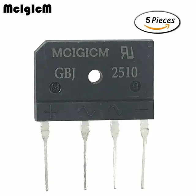 |
| What does a bridge rectifier IC look like? |
 |
| Specifications of GBJ2510 |
This block also contains a capacitor. The capacitor smoothes the pulsating DC voltage. This is the smoothing capacitor or filtering capacitor. To get ripple-free voltage, you need to select a proper capacitance value. The discharging time of the capacitor should be high.
Choosing a smoothing capacitor is also a little bit tricky.
- The first time you might have rippled output, but don't worry
- You just have to adjust the capacitor value, once you get the appropriate capacitor, you get the smooth DC
I discussed this equation in a full-wave rectifier. The equation is helpful for the evaluation of the capacitance value.

I designed a calculator, input appropriate values, you get the desired value of the capacitor.
| Volt | ||
| Volt | ||
| Ohm | ||
| Hertz | ||
| farad |
The Regulator Block:
The voltage regulator maintains a constant voltage level at the output irrespective of no load or full load condition. This block is added in between input and output. It resists any change in input voltage and output load and maintains a constant voltage.
We are using LM317 as a positive voltage regulator. Its specifications are
- Adjustable output voltage ranges from 1.25V to 37V
- Input voltage ranges from 3 to 40V
- Output current 1.5A
Look it is a three-terminal device. As a beginner, you can easily use it in your circuit.
| LM317 Regulator IC |
How do we connect it to the circuit…?
Look at the regulator block. It consists of LM317, two resistors (R1 and R2) and two capacitors (C2 and C3). The capacitors are decoupling capacitors. The resistors make a voltage divider circuit. With the help of these resistors, we can adjust the output.

Designers recommend it is better to set R1 = 240,
There is a targeted output voltage Vout, which is equal to 20V in this case. With the help of the given formula, you can calculate R2.
Here is a calculator, you have to enter any two variables, and it will evaluate the third one.
| Ohm | ||
| Ohm | ||
| Volt |
Conclusion:
I hope you understand the working and operation of the power supply circuit. It is one of the basic circuits. You can find a variety of circuits. If you would able to properly design your power supply unit, then this will power your electronic projects in future.
Some of my favourite books are given below. I always use these books before preparing notes. I recommend all beginners to use these books to master analog electronics. All of them are my favourite.


.jpg)


.jpg)

