Introduction To Algorithms:

Introduction to algorithms, how to write an algorithm using flowchart and pseudocode
Outline:
  • What is an algorithm with examples
  • Properties
  • Representation
    • Pseudocode
    • Flowcharts
  • Examples

An algorithm is a term commonly used in computer science and mathematics. It is a 'problem-solving method’.  You must be familiar with this term. It is the finite set of instructions, logic and step by step procedure execute in a finite amount of time. You can assume it as a to-do list for programmers.
Understand the meaning of the above definition.
A finite set of instructions: there should be a limited number of instructions
Logic: there should be logic, how to solve a particular problem.
Step by step: it consists of a few steps to follow while writing the actual code.
A finite amount of time: It has a finite number of instructions that have to be performed in a finite amount of time.

It is independent of the programming language. It is also called a procedure. The computer can not understand instructions written for human beings. It tells a human being what steps should take to perform a specific task or solve a problem. These steps should write sequentially. Some points to keep in mind while writing an algorithm are:

  • There is no specific format or well-defined standard or fix syntax or language
  • When writing an algorithm for a computer program, we can use code constructs which are common in all programming language like loops, flow control, variable declaration etc.

Example: School Routine
Algorithms are not limited to computing or mathematics. They can be applied to our daily lives. Let's check out this example.
When a kid goes to school, he follows these steps.
  • Wake up early in the morning
  • Brush his teeth and take a bath
  • Wear uniform
  • Have breakfast
  • Get ready for school
  • Go to the bus stand
  • Wait for the transportation
  • Get the bus
  • Go to school

Properties/Characteristics:

An algorithm has the following properties.
Input:
There should be input.
Output:
There must be output as well. Otherwise, the algorithm is useless.
Finiteness:
It should terminate after a finite number of steps.
Determinacy:
Each step should clear, precise and unambiguous.
Effectiveness:
Each step of an algorithm executes effectively.
Generality:
It is equally applicable to all types of inputs. If the input changes the output changes accordingly.

Why do we need algorithms:

When you are writing a computer program, the first step is to write an algorithm. It is independent of the programming language. The purpose of an algorithm is to clearly express what you want to do. The steps which has to follow while solving the problem. In programming, the algorithm is a part of a programmer's job. It is his task to translate an algorithm successfully into a program.

Algorithms are also useful in analyzing computational resources like time to run a program that is computational time, space allocated by a program or memory management, etc.

Representation:

An algorithm can be represented either in pseudocode or flowcharts. Both techniques are used by coders, programmers and designers.

What is pseudocode? How to write an algorithm using pseudocode?

Pseudocode is an arbitrary language for describing algorithms. It only focuses on logic irrespective of the programming language. The purpose is to convey the problem-solving method as a text outline. It can easily be understood by a non-programmer as well. Ideally, pseudocode does not contain syntax and keywords.

What is a flowchart? How to write an algorithm using a flowchart?

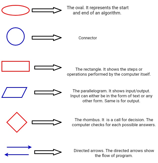
A flowchart is the graphical representation of an algorithm. It consists of different geometrical shapes that describe the flow of a program. It describes the sequence of steps with the help of geometrical shapes involved in a problem. Directed arrows show the flow of the program.


Example 1: A simple program
Addition of two numbers
x = y+z

Pseudocode:

Start
Declare variables: num1, num2, result
Result = num1 + num2
Display result
Stop

Explanation:
In the first step, declare three variables. You need to add two numbers and then store the result in the third variable.

In the second step, the actual task that is addition is performed. This task is performed internally. If you need to display the results you have to write another instruction.

In the third step, there is an instruction for displaying the result or output.

Check the algorithm, it has all the properties that are stated above. Like input, output, finiteness (only three instructions), effectiveness, determinacy and generality.

Flowchart:
Explanation:
This is another way! A pictorial representation. Have a look at it. All the steps are the same. Different shapes show indicate that which is an input/output. Parallelograms show the input and output of the program. The rectangle shows the processing that is the task. Here addition is performed.

Example 2: Algorithm for control flow statements
Find the largest among three different numbers entered by the user

Pseudocode

Start
Declare three variables a, b, c
Read variables a, b, c
Compare variables using a conditional statement
If (a>b && a>c)
   Display 'a’ is the greatest among three numbers

Else if (b>a && b>c)
      Display 'b’ is the greatest among three  numbers

Else
      Display 'c’ is the greatest among three numbers
End

Explanation:

In the first step declare three variables.

In the second step, I write the 'read’ command. It means you ask the user to enter variables. After the user enters these variables, the system will read them.

In the third step, there is a decision making statement. Check if a is greater than or not. If a is greater than b then proceed further. Check whether a is greater than c as well. If this condition is also true, then proceed further.


Flowchart


Explanation:
In the first step, the processing box is there for the declaration of three variables

In the second step, the input/output box is there for input.

In the third step, a rhombus (labelled as a>b) is there. It means some decision making task. It compares two variables at a time.

The same comparison process in the next step.

In the last step again parallelograms are there to display the results/ outputs


Example 3: Algorithm for iterative statements (condition controlled statement do-while loop)
Print number 1 to 5

Pseudocode

Start
Declare and define variable Count = 1
Do

 Display count
 Count = count+1

While count <6
End

Explanation:
In the first step, a variable is declared and defined.

In the second step, a loop begins. A do-while loop.

In the third step, an instruction ‘ Display count’ is there.

The third step repeats until the condition is not satisfied.

In the fourth step, the count variable is incremented by 1.

In the fifth step, the condition is there. How many times does the loop repeat itself? The loop repeats until the variable count becomes 5.

So, the loop iterates 5 times and display the value of count each time.

Flowchart

Important terms:

Condition controlled loops: do-while loop is a condition controlled loop. Its iterations are based on specific conditions. It repeatedly checks whether the condition met or not.

Control flow statements: looping, decision making, branching statements are control flow statements.

Iterative statements: as the name implies it is a repetitive process. for loop is an iterative statement.

Syntax: in simple words, you can say it is the grammar of a programming language. It is a set of rules that specify the correct sequence of words and phrases.

&& (AND AND condition): it is also called logical AND operator. It returns a Boolean value that is either true or false.


Multiple Choice Questions

1. Algorithm is defined as a finite set of instructions executed in a finite amount of time.


  1. A finite amount of time
  2. 10 minutes
  3. Infinite amount of time


2. Algorithm is independent of programming language, so it has no fixed syntax.


  1. A fixed syntax
  2. No fixed syntax


3. Generality of the algorithm means it is valid for various set of inputs. If input changes, the output changes accordingly.


  1. True
  2. False


4. Algorithms are helpful in analyzing computational time.
  1. Wind speed
  2. Computational time
  3. None


5. When you are going to write a computer program, the first step is to write its algorithm.
  1. Algorithm
  2. Code
  3. Name
  4. None


6. Algorithms can be represented by pseudocode or flowcharts.


  1. True
  2. False


7. A single problem has plenty of algorithms.


  1. One
  2. Two
  3. Many
  4. Plenty
  5. c and d


8. Pseudocode is written in a high-level programming language


  1. True
  2. False


Voltage Divider Rule

Voltage Divider Rule - Analysis of Series Circuit Using Voltage Divider Method
In this tutorial, I am going to introduce a top-notch technique for solving series circuits. You can solve a series circuit easily by applying Ohm's law. But Ohm's law has a limitation. You have to know the current flowing through the circuit. This method allows you to find out the voltage across any series component without knowing the current. This method is derived from two very common circuit solving laws, that is Ohm's law and KVL. In this article, I am going to derive the expression of the voltage divider rule as well.

Explanation:

It is only applicable to series circuits where the current remains the same throughout the circuit. Consider a series circuit given below.


Let,

v1 = voltage across R1
v2 = voltage across R2
v3 = voltage across R3
i = total current across the circuit

According to KVL,

v = v1 + v2 + v3
v = iR1 + iR2 + iR3
v = i (R1 + R2 + R3)
i = v/ (R1 + R2 + R3) ….. equation 1

If you want to evaluate voltage across R2, then using Ohm's law

v2 = iR2
i = v2/R2 ….. equation 2

Look at equation 1 and equation 2. Substitute i.

v2/R2 = v/ (R1 + R2 + R3)
v2 = (R2*v) / (R1 + R2 + R3)

Similarly,

v1 = (R1*v) / (R1 + R2 + R3)

v3 = (R3*v) / (R1 + R2 + R3)

This another simple method called the voltage division rule. And the circuit is called a voltage divider because the total voltage is divided into resistances. The larger the resistance, the larger the voltage drop across that resistance.

Solved Examples:

In the previous article (resistors in series), I analysed and solved a series circuit using Ohm's law. In this tutorial, I am going to solve the same examples with the help of the voltage divider rule.

Example 1:
A 12 V source is connected with these resistances: 1kΩ, 2kΩ and 4kΩ. How much current flows through the 4kΩ resistance?


I solved this problem in my previous tutorial.
Another way to solve this problem.
The total resistance will be the sum of all individual resistances.

RT = R1 + R2 + R3
RT = (1+2+4) kΩ
RT = 7 kΩ
Voltage across 4kΩ or R3 = v3
v3 = (R3/RT).V
v3 = (4k/7k).12
v3 = 6.85V

Current flows through R3
i = v3/R3
i = 6.85/4k
i = 1.7mA

Note: The current 1.7mA is the total current flowing through the series circuit.
Voltage Divider Rule

Series Resistors | Equivalent Series Resistance | Formula Of Series Resistance

Series Resistors | Equivalent Series Resistance | Formula Of Series Resistance


Current & Voltage Through Series Resistors: Analysis of Series Circuits:


Before starting my tutorial on series-connected resistors, I would like to recall series circuits.
“Two elements connected in such a way that they share a single node exclusively.”

Similarly, two resistors are connected in series, when they share a single node exclusively.

Properties Of Series Connected Resistors:

  • Current remains the same in every series-connected resistor
  • Another property of the series circuit is the voltage division property. The voltage is divided proportionally to all resistors. The larger the resistance value, the greater will be the voltage drop across that resistance.

Formula Of Resistance In Series:

Apply Ohm's law to the circuits below,

Circuit 1:

The voltage drop across R1 is va
va = iR1

The voltage drop across Ris vb
vb = iR2

The total voltage across circuit the is the sum of voltage drops across R1 and R2
v1 = va + vb … equation 1
Circuit 2:

Voltage across Req
v2 = iReq … equation 2

Observations and Calculations:

Have a close look at both circuits. v1 and v2 are the same that is 10V. I take same the same voltage sources, and the current flowing through the circuit remains the same. The difference is the number of resistances in the circuits. Circuit 1 has R1 and R2. and Circuit 2 has only Req.

Look at circuits 1 and 2,

v1 = v2
va + vb = v2

iR+ iR2 = iReq

From observations and calculations, we can conclude that

Req = R1 + R2


Analysis of series circuits
Figure: Electrically equivalent circuits


Implying that we can replace R1 and R2 with a single equivalent resistor. Similarly, we can replace N series resistors with a single equivalent resistor. This is because Req has the same voltage drop across terminals a & b. Also, current and power relationships in the equivalent circuit will remain the same.

The equivalent resistance of a series-connected resistor is the algebraic sum of all the individual resistances.

Req = R1 + R2 + R3 + …..RN

Analysis Of Some Confusing Series Circuits:


Circuit 1:
Circuit 1 is a series circuit. All 5 components are serially connected.

Circuit 2:
It is not a series circuit.

Circuit 3:
It is also a series circuit. It contains multiple sources and resistors. All are connected in series with each other.

Circuit 4:
It is not a series circuit.

Solved Examples:

Example 1:
A 12 V source is connected with these resistances: 1kΩ, 2kΩ and 4kΩ. How much current flows through the 4kΩ resistance?

Solution:
Figure: Draw the circuit with the help of given data


Before calculating the current, you have to find out the total or equivalent resistance of the circuit. After evaluating the total or equivalent resistance, apply Ohm's Law to find out the current through the circuit.

The total resistance will be the sum of all individual resistances.

RT = R1 + R2 + R3
RT = (1+2+4) kΩ
RT = 7 kΩ

Current remains the same  in a series circuit
Current through the 4kΩ is:

i = v/RT
i = 12/7
i = 1.7 mA


Example 2:
From the following data, evaluate the resistance value that should be connected in series to limit the load current to 5mA.
R= load resistance = 250Ω
RS = series resistance =?
IT = total current required by the load resistance

First of all, draw a circuit and label it with the given data.


Figure: Circuit diagram for example 2

RT = total resistance = RS + RL = RS + 250
RS = RT -250
IT = V/RT
5*10-3 = 5/RT
RT = 1000Ω
RS = 750Ω

Conclusion:

I discussed series-connected resistors in detail. As far as practical applications are concerned, resistors in series are frequently used to limit the voltage. Such circuits are called voltage divider circuits. In complex circuits, we frequently use this technique to simplify circuit analysis.
 There is another way of solving series circuits without knowing the current values. This method is known as Voltage Divider Rule.


Power Dissipation In Resistors

Work Energy & Power

 Applications Of Ohm's Law | Work Energy & Power:

Ohm's law is applicable in determining the power dissipation in resistive elements.

Energy:

Energy and work have the same units, that is joules. Energy is defined as the ability to do work. There are many forms of energy, like electrical, mechanical, kinetic thermal and potential. Electricity is a form of energy. Energy can change from one form to another will result in heat, which is also an important form of energy, when you study electronics and electrical engineering. The change of energy from one form to another is called energy transformation. Heat changes the electrical properties of materials. A battery is a source of electrical energy and can do work.

Energy = Power*Time

Work:

Work is defined as an expenditure of energy. The amount of work done is the amount of energy transformed.

Power:

Power is the rate of change of energy or rate of energy transformation or the rate at which work is done. When studying electricity, work is done whenever current flows through the circuit. The greater the flow of current, the more work is done and more power is consumed.
When current flows through a certain element, electrical energy is converted into heat energy or some other form of energy. The rate at which energy is converted depends on the voltage across and current through that element.

Power = Current*Voltage
P = I*V

When current flows through the resistor, it becomes hot.  And hence electrical energy is converted into heat energy. If the current flows through the fan, it means electrical energy is converted into mechanical energy and heat energy. And the rate at which energy is transformed into another form is termed Power and measured in watts.


Power Ratings:
As a technology enthusiast or student of electrical and electronics engineering, you must see the power ratings printed on the appliances. The maximum power an appliance can tolerate without being damaged is its power rating.

Now understand in simple terms. If we apply electrical power to a device that is less than its rated power then its efficiency is less than the rated or expected. Or if we apply electrical power to a device that is higher than its rated power then its efficiency would be higher than the rated efficiency and the device may be damaged.

Energy  consumption = power ratings * time
E = P*t

An Introduction to Kilowatts Hours:


“The kilowatt-hour (symbolized kW⋅h as per SI) is a composite unit of energy equivalent to one kilowatt (1 kW) of power sustained for one hour. One watt is equal to 1 J/s. One kilowatt-hour is 3.6 megajoules, which is the amount of energy converted if work is done at an average rate of one thousand watts for one hour.”

The higher the power the more energy is converted at a given amount of time. If you run an appliance for a longer period then it consumes more energy (electricity). Let's have a look at different appliances and their power ratings and energy consumption.


Electrical Appliances
Operating Voltage
Time
Power Ratings
Energy Consumption
Kilowatt hours (kwh)
Philips Hair Dryer
220 - 240 V
30 min
1000 - 1200 W
E = 1000*30*60 = 1,800,000 J
E = 1kw * 0.5 hours = 0.5 kwh
Philips Hair Straightener
220 V
15 min
65W
E = 65*15”60 = 58,500J
--
Black & Decker Iron
220 V
10 min
1500W
E = 1500*10*60 = 900,000J
E = 1.5 kw * ⅙ hours = 0.25 kwh

Look at Philips hairdryer ratings. When the operating voltage is 220 V then the power rating is 1000W. And when operating voltage 240 V then the power rating is 1200 W.

Change In Power:

According to Ohm’s law, if the voltage applied to the circuit changes, the current flowing through the circuit changes in the same proportion (as the voltage is directly proportional to current). In the same manner, if the resistance in a circuit changes, the current drawn by the circuit changes, as long as the voltage across the circuit remains the same. Similarly, if voltage or current through the circuit changes, the power consumption of the circuit also changes.
V = IR   Eq 1
P = IV   Eq 2

With the help of simple algebra, we can evaluate the following equations.

P = I2R  Eq 3
P = V2/R  Eq 4

From the above equation, we can conclude that power dissipation in resistors is a non-linear function of current and voltage.

Example: Calculate the power taken by the circuit. V = 20V, I = 0.1A.
Calculate power taken by the circuit if the voltage applied to the circuit doubles.

P = IV
P = 20*0.1
P = 2W

Now applied voltage doubles, then

P = IV
P = 40*0.1
P = 4 W


Popular Posts