Voltage Divider Rule

Voltage Divider Rule - Analysis of Series Circuit Using Voltage Divider Method
In this tutorial, I am going to introduce a top-notch technique for solving series circuits. You can solve a series circuit easily by applying Ohm's law. But Ohm's law has a limitation. You have to know the current flowing through the circuit. This method allows you to find out the voltage across any series component without knowing the current. This method is derived from two very common circuit solving laws, that is Ohm's law and KVL. In this article, I am going to derive the expression of the voltage divider rule as well.

Explanation:

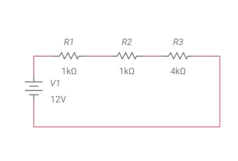
It is only applicable to series circuits where the current remains the same throughout the circuit. Consider a series circuit given below.


Let,

v1 = voltage across R1
v2 = voltage across R2
v3 = voltage across R3
i = total current across the circuit

According to KVL,

v = v1 + v2 + v3
v = iR1 + iR2 + iR3
v = i (R1 + R2 + R3)
i = v/ (R1 + R2 + R3) ….. equation 1

If you want to evaluate voltage across R2, then using Ohm's law

v2 = iR2
i = v2/R2 ….. equation 2

Look at equation 1 and equation 2. Substitute i.

v2/R2 = v/ (R1 + R2 + R3)
v2 = (R2*v) / (R1 + R2 + R3)

Similarly,

v1 = (R1*v) / (R1 + R2 + R3)

v3 = (R3*v) / (R1 + R2 + R3)

This another simple method called the voltage division rule. And the circuit is called a voltage divider because the total voltage is divided into resistances. The larger the resistance, the larger the voltage drop across that resistance.

Solved Examples:

In the previous article (resistors in series), I analysed and solved a series circuit using Ohm's law. In this tutorial, I am going to solve the same examples with the help of the voltage divider rule.

Example 1:
A 12 V source is connected with these resistances: 1kΩ, 2kΩ and 4kΩ. How much current flows through the 4kΩ resistance?


I solved this problem in my previous tutorial.
Another way to solve this problem.
The total resistance will be the sum of all individual resistances.

RT = R1 + R2 + R3
RT = (1+2+4) kΩ
RT = 7 kΩ
Voltage across 4kΩ or R3 = v3
v3 = (R3/RT).V
v3 = (4k/7k).12
v3 = 6.85V

Current flows through R3
i = v3/R3
i = 6.85/4k
i = 1.7mA

Note: The current 1.7mA is the total current flowing through the series circuit.
Voltage Divider Rule

Series Resistors | Equivalent Series Resistance | Formula Of Series Resistance

Series Resistors | Equivalent Series Resistance | Formula Of Series Resistance


Current & Voltage Through Series Resistors: Analysis of Series Circuits:


Before starting my tutorial on series-connected resistors, I would like to recall series circuits.
“Two elements connected in such a way that they share a single node exclusively.”

Similarly, two resistors are connected in series, when they share a single node exclusively.

Properties Of Series Connected Resistors:

  • Current remains the same in every series-connected resistor
  • Another property of the series circuit is the voltage division property. The voltage is divided proportionally to all resistors. The larger the resistance value, the greater will be the voltage drop across that resistance.

Formula Of Resistance In Series:

Apply Ohm's law to the circuits below,

Circuit 1:

The voltage drop across R1 is va
va = iR1

The voltage drop across Ris vb
vb = iR2

The total voltage across circuit the is the sum of voltage drops across R1 and R2
v1 = va + vb … equation 1
Circuit 2:

Voltage across Req
v2 = iReq … equation 2

Observations and Calculations:

Have a close look at both circuits. v1 and v2 are the same that is 10V. I take same the same voltage sources, and the current flowing through the circuit remains the same. The difference is the number of resistances in the circuits. Circuit 1 has R1 and R2. and Circuit 2 has only Req.

Look at circuits 1 and 2,

v1 = v2
va + vb = v2

iR+ iR2 = iReq

From observations and calculations, we can conclude that

Req = R1 + R2


Analysis of series circuits
Figure: Electrically equivalent circuits


Implying that we can replace R1 and R2 with a single equivalent resistor. Similarly, we can replace N series resistors with a single equivalent resistor. This is because Req has the same voltage drop across terminals a & b. Also, current and power relationships in the equivalent circuit will remain the same.

The equivalent resistance of a series-connected resistor is the algebraic sum of all the individual resistances.

Req = R1 + R2 + R3 + …..RN

Analysis Of Some Confusing Series Circuits:


Circuit 1:
Circuit 1 is a series circuit. All 5 components are serially connected.

Circuit 2:
It is not a series circuit.

Circuit 3:
It is also a series circuit. It contains multiple sources and resistors. All are connected in series with each other.

Circuit 4:
It is not a series circuit.

Solved Examples:

Example 1:
A 12 V source is connected with these resistances: 1kΩ, 2kΩ and 4kΩ. How much current flows through the 4kΩ resistance?

Solution:
Figure: Draw the circuit with the help of given data


Before calculating the current, you have to find out the total or equivalent resistance of the circuit. After evaluating the total or equivalent resistance, apply Ohm's Law to find out the current through the circuit.

The total resistance will be the sum of all individual resistances.

RT = R1 + R2 + R3
RT = (1+2+4) kΩ
RT = 7 kΩ

Current remains the same  in a series circuit
Current through the 4kΩ is:

i = v/RT
i = 12/7
i = 1.7 mA


Example 2:
From the following data, evaluate the resistance value that should be connected in series to limit the load current to 5mA.
R= load resistance = 250Ω
RS = series resistance =?
IT = total current required by the load resistance

First of all, draw a circuit and label it with the given data.


Figure: Circuit diagram for example 2

RT = total resistance = RS + RL = RS + 250
RS = RT -250
IT = V/RT
5*10-3 = 5/RT
RT = 1000Ω
RS = 750Ω

Conclusion:

I discussed series-connected resistors in detail. As far as practical applications are concerned, resistors in series are frequently used to limit the voltage. Such circuits are called voltage divider circuits. In complex circuits, we frequently use this technique to simplify circuit analysis.
 There is another way of solving series circuits without knowing the current values. This method is known as Voltage Divider Rule.


Power Dissipation In Resistors

Work Energy & Power

 Applications Of Ohm's Law | Work Energy & Power:

Ohm's law is applicable in determining the power dissipation in resistive elements.

Energy:

Energy and work have the same units, that is joules. Energy is defined as the ability to do work. There are many forms of energy, like electrical, mechanical, kinetic thermal and potential. Electricity is a form of energy. Energy can change from one form to another will result in heat, which is also an important form of energy, when you study electronics and electrical engineering. The change of energy from one form to another is called energy transformation. Heat changes the electrical properties of materials. A battery is a source of electrical energy and can do work.

Energy = Power*Time

Work:

Work is defined as an expenditure of energy. The amount of work done is the amount of energy transformed.

Power:

Power is the rate of change of energy or rate of energy transformation or the rate at which work is done. When studying electricity, work is done whenever current flows through the circuit. The greater the flow of current, the more work is done and more power is consumed.
When current flows through a certain element, electrical energy is converted into heat energy or some other form of energy. The rate at which energy is converted depends on the voltage across and current through that element.

Power = Current*Voltage
P = I*V

When current flows through the resistor, it becomes hot.  And hence electrical energy is converted into heat energy. If the current flows through the fan, it means electrical energy is converted into mechanical energy and heat energy. And the rate at which energy is transformed into another form is termed Power and measured in watts.


Power Ratings:
As a technology enthusiast or student of electrical and electronics engineering, you must see the power ratings printed on the appliances. The maximum power an appliance can tolerate without being damaged is its power rating.

Now understand in simple terms. If we apply electrical power to a device that is less than its rated power then its efficiency is less than the rated or expected. Or if we apply electrical power to a device that is higher than its rated power then its efficiency would be higher than the rated efficiency and the device may be damaged.

Energy  consumption = power ratings * time
E = P*t

An Introduction to Kilowatts Hours:


“The kilowatt-hour (symbolized kW⋅h as per SI) is a composite unit of energy equivalent to one kilowatt (1 kW) of power sustained for one hour. One watt is equal to 1 J/s. One kilowatt-hour is 3.6 megajoules, which is the amount of energy converted if work is done at an average rate of one thousand watts for one hour.”

The higher the power the more energy is converted at a given amount of time. If you run an appliance for a longer period then it consumes more energy (electricity). Let's have a look at different appliances and their power ratings and energy consumption.


Electrical Appliances
Operating Voltage
Time
Power Ratings
Energy Consumption
Kilowatt hours (kwh)
Philips Hair Dryer
220 - 240 V
30 min
1000 - 1200 W
E = 1000*30*60 = 1,800,000 J
E = 1kw * 0.5 hours = 0.5 kwh
Philips Hair Straightener
220 V
15 min
65W
E = 65*15”60 = 58,500J
--
Black & Decker Iron
220 V
10 min
1500W
E = 1500*10*60 = 900,000J
E = 1.5 kw * ⅙ hours = 0.25 kwh

Look at Philips hairdryer ratings. When the operating voltage is 220 V then the power rating is 1000W. And when operating voltage 240 V then the power rating is 1200 W.

Change In Power:

According to Ohm’s law, if the voltage applied to the circuit changes, the current flowing through the circuit changes in the same proportion (as the voltage is directly proportional to current). In the same manner, if the resistance in a circuit changes, the current drawn by the circuit changes, as long as the voltage across the circuit remains the same. Similarly, if voltage or current through the circuit changes, the power consumption of the circuit also changes.
V = IR   Eq 1
P = IV   Eq 2

With the help of simple algebra, we can evaluate the following equations.

P = I2R  Eq 3
P = V2/R  Eq 4

From the above equation, we can conclude that power dissipation in resistors is a non-linear function of current and voltage.

Example: Calculate the power taken by the circuit. V = 20V, I = 0.1A.
Calculate power taken by the circuit if the voltage applied to the circuit doubles.

P = IV
P = 20*0.1
P = 2W

Now applied voltage doubles, then

P = IV
P = 40*0.1
P = 4 W


Best Electronic Components Kits - Electronic Component Storage

Best kits for electronics components
"Clutter in your physical surroundings will clutter your mind and spirit."

Whether you are a student, hobbyist, amateur or a professional, it is a good practise to keep your things properly, neat and clean. In this article I will explain the way in which you maintain your discrete electronic components.
As a female I used to keep my things properly, in a well organiser manner. I have a limited space, where I put all my stuff. So I am always looking for organiser, shelves. The purpose of organising your stuff is to store your components, prevent them from dust, keep it away from kids, and you get them back easily when you need them.

All In One Kit:


After a lot of search, I found this kit. I like it very much. Now look at it!!

View on Amazon


It seems decent, and economical as well. It is really good for storing discrete electronic components like diodes, resistors, capacitors, transistors, different ICs etc.
“Color is a power which directly influences the soul.” ~Wassily Kandinsky.

 Another colorful kit, contains all items (235 pieces) in a single box. It contains wires, LEDs, potentiometers, resistors, capacitors. A good starter kit for beginners.


Storage Kit:

Here is another kit I have found. It is also eye-catching, colourful organiser kit, specifically for electronic components.


View on Amazon


Resistor Kit:

Look at this amazing kit. It only contains resistors from 0 ohms to 1 mega ohms. It is really helpful to sort different resistors.

View on Amazon

Capacitors Kit:

Resistors and capacitors are most commonly used electronic components. You need to have many different values of capacitors in a circuit. It is good to have a kit for them as well. The kit contains 696 pieces. 24 different values of electrolytic capacitors. Values ranges from 0.1uF to 1000uF and voltage ratings are 10V, 16V, 25V and 50V.

View on Amazon


Ohm's Law - Statement, Explanation, Calculations

Ohm's Law Statement, Explanation and Calculations


This is the very first law related to electricity. It was presented by German physicist Georg Simon Ohm (1787 - 1854). The importance of this law is evident from the fact that it is still valid and used in almost all the design, troubleshooting and repairing of any electrical system. It is applicable to all linear circuits (a circuit is linear if voltage and current graph is a straight line).  It is also applicable to both AC or DC circuits. It describes the relationship between three basic quantities, that is, current, voltage and resistance.

The scientist performed series of experiments, at that time there were no electrical measuring instruments. In today's world we can easily verify Ohm's law because we have measuring instruments.

The empirical law describes the linear relationship between current and voltage.
“At constant temperature, it takes
one volt of electrical pressure (voltage) to push one ampere of current through one ohm resistor”

OR
“At constant temperature, current (I) through the conductor is directly proportional to voltage (V) applied across its terminals”

Mathematically,
I ∝ V
V = I*R
I = V/R
R = V/I
I = G*V
R = 1/G

Where, R is constant of proportionality called resistance. Resistance is inversely proportional to conductance (G). R is same for a single material. The value of R (resistance) depends on material, its dimensions and temperature. I explained temperature dependence of resistances here.
R = ρ*L/A    Equation 1

The above equation 1 shows the resistance of a resistor depends on its dimensions ( length (L) and area (A) of conductor).

Rt = Ro (1+ αot)     Equation 2

Equation 2 shows temperature dependence of conductors. It is measured in unit Ohms and represented by Greek letter Omega (Ω).


Understanding Ohm’s Law With Simple Analogy


Ohm's Law and its analogy
Beginners are always confuse with theory and mathematical relationships. Here is a simple analogy for Ohm's law.

Consider two pipes of different dimensions (different diameters and hence different area A).

Water easily passes through pipe A because of larger area. It means water passes through less resistive path easily. While in pipe B less water comes out because it offers more resistance for the flow of water.

In this example, voltage is analogous to water pressure. The pipe itself analogous to resistance. It provides the path for the water. If the pipe is narrow, the water flow is less as compared to the broad pipe
Water is analogous to current (electrons) , which flows e region of higher pressure to lower pressure. In the same way current flows from higher potential to lower potential (voltage).

Similarly if consider current ( electrons) instead of water. We get similar observations.

Understanding Ohm’s Law With Simple Experiment

A simple electric circuit is shown. A voltage source (battery) is connected across load resistor (lamp). A connecting wire is a conductor. When circuit is closed, current flows from battery to the lamp, and hence lamp illuminates.

Ohm’s law describes the way in which current flows through the conductor when external voltage is applied  From observations we conclude:
  • The current is directly proportional to source voltage
  • The current is inversely proportional to the resistance. The higher the resistance, the lower the current

Limitations Of Ohm's Law:

  • It is valid for metallic conductors only
  • Metallic conductors obey Ohm's law at moderate temperatures only
  • All semiconductor devices like diodes, vacuum tubes, transistors, thermistors etc don't obey Ohm's law. They are non-ohmic devices
IV curve for ohmic conductor and non ohmic conductor
IV characteristics curve of an ohmic and non-ohmic conductor


Popular Posts