Construction of Resistors - Some basic types
Outline:
- Wire wound resistors
- Carbon composition resistors
- Carbon film resistors
- Metal film resistors
What is inside the wire wound resistors?
Wire wound resistors are the oldest types of resistors. They are suitable for high power and high precision applications. You can imagine the structure of resistor by its name, a spiral helix wound on a tube.
A resistant wire (made from alloy) with high resistivity value is wounded on an insulated core such as ceramic or glass. The value wire wound resistor is determined by this formula,
R = ρ*L/A
The larger the wire the larger the resistance. the larger the cross sectional area, the lower the resistance. To make larger resistance a large thin wire is required.
Pure metals have high temperature coefficient because they are more like to change their resistances as temperature changes. (Effect of temperature on resistance of a conductor). Metal alloys are used because they low temperature coefficient (TCR). They are stable over wide range of temperature. They can satisfactorily work beyond their temperature and power ratings.
For example a wire wound resistor has a operating temperature range is -65°C to +125°C. But it can withstand temperature ranges from -55°C to +150°C.
Similarly a wire wound resistor can dissipate 10 times their rated power for few seconds.
Disadvantages:
Wire wound resistors have inductance as well because of its structure. They possess advantages and disadvantages of an inductor as well including self and mutual inductance. They are not suitable for high frequency applications because of inductive and capacitive effect. In case of overload, the temperature can shoot up to 700°C, before the resistor operation come to an end. It can cause a great hazard if you directly mount a wire wound resistor on a printed circuit board.
Application:
Wire wound resistors are most stable and most expensive types of resistors. They are available in 0.1 to 100 kilo ohm range. They dissipate power up to 10W. They are commonly used as
- Circuit breakers or fuses. Since they has high power capabilities, they can use as circuit breakers or a part of circuit breaker
- They can be used as potentiometer. For example in stereo system wire wound resistors can be used because of high precision. Another use of such potentiometers are in TV transducers because they can sustainable at high temperatures
- Due to inductive property, these can be used as current sensors
What is inside the carbon composition resistors?
Carbon composition resistors are constructed by mixing carbon powder and a non conductive material (for example clay). The mixture is then solidified by heat and compressed in the form of stick or rod. This rod is a resistive element. The whole structure is surrounded by insulated paint with colour codes printing. The leads are made from tinned copper.
Carbon is a good conductor of electricity, more amount of carbon added, more current flows easily. It means the material has less resistance.
The resistance value is determined by
R = ρ*L/A
- The amount of carbon mixture
- The length of the carbon mixture
- The cross sectional area of the carbon mixture
The resistance value is determined by the amount of carbon in the rod. The higher the amount of carbon in the mixture the lower the resistance.
The greater the length of the mixture the higher the resistance.
The larger the cross sectional area of the mixture the lower the resistance.
Specifications:
Resistance range 0.1 ohm to 22 mega ohms
Tolerance 5% , 10%, 20%
Power ratings 1 W
Temperature Range -55°C to +120°C
TCR 1200 ppm/° C
Advantages:
- They are least expensive
- They are used in audio amplifiers because of their low noise capabilities
- Ideal for high frequency application
Disadvantages:
- They can only used in low heat dissipation circuits
- Not suitable for those applications where humidity and temperature are not important. When these resistors exposed to humidity, water absorption may change resistance value up to +/- 15%
- They can not use in high precision applications
Applications:
- Carbon composition resistors are widely used in general purpose electronic circuits
What is inside carbon film resistors?
Carbon film resistors are formed by depositing a thin layer of carbon film over ceramic rod. This carbon film acts as a resistive material. It means it provides some resistance to the current flowing through the material. While the ceramic rod acts as an insulating material, that doesn't allow heat and electricity through it.
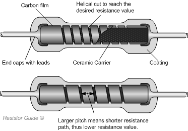
The resistance of carbon film resistors is determined by adjusting the thickness of carbon layer and helical cut. This is done by an automated feedback process. The thickness of rod increases and resistance decreases. The resistance value can vary by trimming the carbon film in helical cut (these cuts are spiral in shape). For larger resistance the pitch of the spiral is reduced.
R = ρ*L/A
Let's understand with the help of above equation. The smaller pitch in carbon film provides less path for electrons (more resistive path) while larger pitch in carbon film provides more path for electrons (less resistive path). It means cross sectional area is inversely proportional to resistance. The length of the carbon film increases the resistance because electrons have to travel more.
Specifications:
Resistance value 1 ohm to 10 Mega ohms
Tolerance 2%, 5% ,10% and 20%
Power ratings upto 2 W
Temperature range upto 350°C
Advantages:
- Less expensive than carbon composition resistors
- Stable in humid weather
- Low noise
Disadvantages:
- High negative temperature coefficient of resistance (means the resistance of the material drops with an increase in temperature)
Applications:
- Lasers
- Radars
- X rays
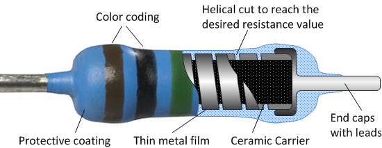
What is inside metal film resistors?
Another type of fixed resistors. A conductive layer deposits on a non-conductive core (usually ceramic core). The conductive layer is a metal film, which is deposited on a ceramic rod.
Did you notice, the construction of metal film resistors are same as carbon film resistors. These days metal film resistors replace carbon film resistor. They don't change their value with age.
 |
| P.C. Resistor Guide film.metal_film_resistor_schematic.png (550×213) |
The resistance value can be determined by using the formula
R = ρ*L/A
The resistance of a resistor depends on thickness of the deposited metal film (50 nm - 250 nm). The resistance of a resistor can be varied with the length and area of the metal. Different metals have different coefficient of resistivity (ρ). Nickel chromium is a commonly used resistive material. Desired resistance can be achieved by trimming metal film in helical cut. For larger resistance, the pitch of spiral is reduced.
Specifications:
Resistance value 1 ohm to 10 Mega ohms
Tolerance 0.1%, 0.25% ,0.5%, 1% and 2%
Power ratings less than 3 W
Temperature range upto
TCR 50 and 100 ppm/K
Advantages:
Metal film resistors have better tolerance range than carbon film resistors.
- Metal film resistors tolerance value upto 2% , while carbon film resistors tolerance value upto 20%
- Low noise, high stability
- Better power dissipation capabilities
Disadvantages:
- Higher cost
- Can not handle over current, voltage surges
- Very low power ratings


.jpg)


.jpg)


Thanks for sharing the best information and suggestions, I love your content, and they are very nice and very useful to us. If you are looking for the best Film Resistors, then visit Dropmart.in. I appreciate the work you have put into this.
ReplyDelete